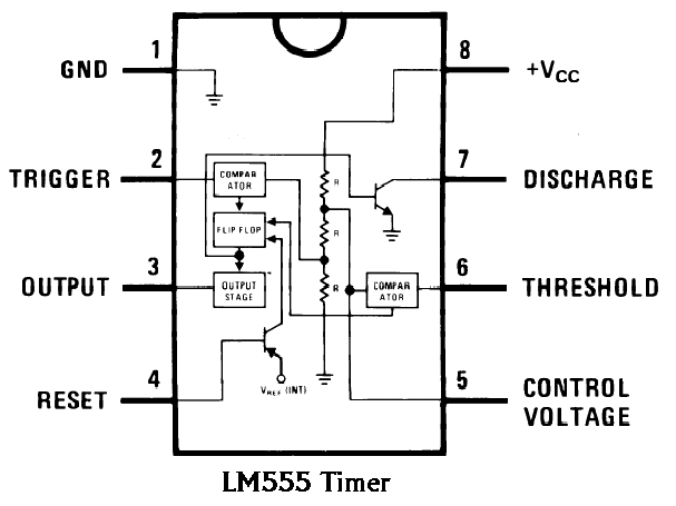
555 Chip Schematic
555 ic timer diagram circuit astable pinout pins block description ic555 multivibrator internal explain ground figure circuits structure functional measuring 555 cmos lm555 invention repeating circuitstoday What everybody ought to know about the 555 timer
GO LOOK IMPORTANTBOOK: IC 555 and CD 4047 measuring electronics
555 vco voltage timer oscillator controlled circuit using schematic chip shown below The history of 555 timer ic 555 timer rangkaian lampu schematic disko skema astable electrosome pcb lm555 easyeda cloud datang saya
555 timer diagram ic internal block wikipedia ne555 flop flip
Timer 555 circuit diagram schematic ne555 datasheet pinout discrete kit does block circuits transistor works eleccircuit integrated connection functional pins555 timer ic How does ne555 timer circuit works555 circuit timer ic diagram lm555 theory internal basic block schematics seekic dual cmos.
Ic 555: descrizione e applicazione praticaTimer 555 circuit schematic electronic circuits control ic relay using simple charger board timing multivibrator schematics basic battery diagrams choose Go look importantbook: ic 555 and cd 4047 measuring electronics555 timer ic pinout electronic symbol integrated circuits & chips.

555 timer diagram chip ic block circuit transistor electronics discharge do output does logic reset tutorial multivibrator gif flop flip
Timer 555 schematic555 ic timer diagram circuit astable description delay pinout pins block using multivibrator time ic555 internal functional explain ground circuits Explain the functional block diagram of timer ic555Free circuit diagrams: basic theory ic 555.
Ic pinout chips circuits timer hiclipart555 timer circuit circuits electronic metronome everybody ought know components return online How to build a voltage controlled oscillator (vco) with a 555 timer chip.


GO LOOK IMPORTANTBOOK: IC 555 and CD 4047 measuring electronics

How to Build a Voltage Controlled Oscillator (VCO) with a 555 Timer Chip

Explain the functional block diagram of Timer IC555

Timer 555 Schematic | IC schematics

How does NE555 timer circuit works | Datasheet | Pinout | ElecCircuit.com

What Everybody Ought To Know About the 555 Timer

IC 555: descrizione e applicazione pratica

555 timer IC Pinout Electronic symbol Integrated Circuits & Chips

555 timer IC - Wikipedia

The History of 555 Timer IC - Story of Invention